Posts

Showing posts from 2011

Producing IPv6 traceroute results in HTML format using NMAP

Image
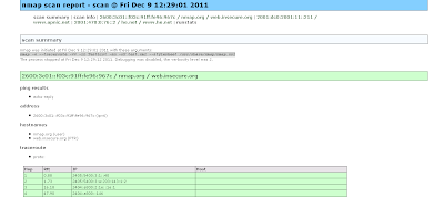
I searched how we can display the IPv6 trace-route results to web in automated manner. There may be different PHP / perl modules but using nmap trace route option we can archive similar fashion. we can have the list of hosts separated by space nmap.org www.apnic.net he.net we can use following command to create the XML output. nmap -6 --traceroute -vv -iL TestList -sn -oX test.xml --stylesheet /usr/share/nmap/nmap.xsl -6 to enable IPv6 -vv increase the verbosity of the oubput --sn no port scan -oX output XML --stylesheet where to find { to translate from XML to HTML } xsltproc test.xml --output test.html

PPTP Server as Cisco for Mikrotik Client

Image
Following configuration explains the Cisco as PPTP server and connecting two sites: Following Configuration needed to enable the VPDN and default server: vpdn enable ! vpdn-group Mtik ! Default PPTP VPDN group accept-dialin protocol pptp virtual-template 1 interface Virtual-Template1 ip unnumbered Loopback0 peer default ip address pool IPPOOL1 ppp encrypt mppe auto required ppp authentication ms-chap-v2 ms-chap pap ip local pool IPPOOL1 192.168.150.10 192.168.150.224 Few more additional things we need to keep the same ip address for the user: aaa new-model ! ! aaa authentication ppp default local aaa authorization network default local ! aaa attribute list Gobi attribute type addr 192.168.150.13 service ppp protocol ip mandatory attribute type route "10.0.0.0 255.255.255.0 192.168.150.13" attribute type interface-config "description Gobi-test" Finally apply the attribute list to the user: username gobi password 0 test username gobi aaa attri

l2tpv3 configuration reference

Image
Reference Comparing , Designing and Deploying VPNs chap - 02 : L2TPv3 is the enhanced version of L2TPv2 protocol. Mikrotik uses L2TPv2 i suppose but it offer another similar tunneling mechanism as EOIP. L2TPv3 in cisco provides Pseudo-wire services to the customer. L2TPv3 only require the IP connectivity between peers but it can transport Ethernet, 802.1Q , HDLC, PPP framerelay etc. Advantage over MPLS is the customer having the full control of their routing domain. L2TP depolyment methods having 3 topologies LAC - LNS , LNS - LNS , LAC - LAC Following Diagram explain simple LAC - LAC L2TPv3 setup. It uses two types of messages: control connection messages - used for signaling between LCEs session data messages - Used to transport layer 2 protocols and connections Data channel Message Header having Session ID & cookie to correctly associate with the tunnel Deploying dynamic Pseudowires session 1) configure CEF - Its default in IOSs now. 2) configure a loopback in

Modifying the Wireshark Column.

Image
Basically i had a packet capture file where i need to check the ICMP sequence number to check any packet drops. going each packet one by one and finding out the sequence number is a tedious job. So i was looking to find a way to add another column to display the icmp sequence number. Its quite easy 1) Go to Edit -> Preference 2) Add a new column and select the field type as custom and give the filter as icmp.seq 3) You can see following result . According to our requirement we can modify the field type.

Cost Effective 1 Port Terminal Server Rs232 using mikrotik / 3G

out of band management is critical for the network operation. when searching solution for console access through rs232 and 3G i came across Mikrotik serial connection option. I haven't tested the 3G setup yet but quite impressive options available in 79$ Mikrotik router for RS232 access: 1st have to set the baud-rate and similar settings : [admin@Console_Tik] > port export # jan/02/1970 00:32:05 by RouterOS 5.5 # software id = WE49-11I9 # /port set 0 baud-rate=9600 data-bits=8 flow-control=none name=serial0 parity=none \ stop-bits=1 /port firmware set directory=firmware [admin@Console_Tik] > 2nd if we are using for console access we need to disable the console port option on mikrotik as follows : [admin@Console_Tik] > system console print Flags: X - disabled, U - used, F - free # PORT TERM 0 X serial0 vt102 From mikrotik we can directly access the co

shorten the MPLS IOS commands

when it comes to mpls + vrf we can observe some lengthly commands.. R3#show bgp vpnv4 unicast vrf CusA BGP table version is 7, local router ID is 192.168.254.3 Status codes: s suppressed, d damped, h history, * valid, > best, i - internal, r RIB-failure, S Stale Origin codes: i - IGP, e - EGP, ? - incomplete Network Next Hop Metric LocPrf Weight Path Route Distinguisher: 65001:100 (default for vrf CusA) *> 192.168.200.0 192.168.100.1 0 0 65100 i *>i192.168.210.0 192.168.254.8 0 100 0 65101 i how to shorten these commands as usual we can use aliases eg: alias exec shbgpvrf show bgp vpnv4 unicast vrf R3#shbgpvrf CusA BGP table version is 7, local router ID is 192.168.254.3 Status codes: s suppressed, d damped, h history, * valid, > best, i - internal, r RIB-failure, S Stale Origin codes: i - IGP, e - EGP, ? - incomplete Network Next Hop Metric L

MPLS LAB for experiment.

Image
This is the lab prepared using the L2IOU (http://tinyurl.com/69j77ju ) NETMAP : 1:0/0 3:0/0 1:0/1 4:0/0 2:0/0 3:0/1 2:0/1 4:0/1 3:0/2 5:0/0 4:0/2 5:0/1 5:0/3 6:0/0 5:0/2 7:0/1 6:0/1 7:0/0 7:0/2 8:0/0 7:0/3 9:0/0 8:0/1 10:0/0 9:0/1 11:0/0 root@box:/home/tc# cat labstart_mpls #!/bin/sh if [ "`pgrep i86bi`" ] then echo "" echo "" echo "The lab is already loaded" echo "" echo "" else echo "" echo "" echo please wait for the Lab to be loaded.. echo "" ./wrapper -m ./i86bi_linuxl2-upk9-ms.M -p 2001 -- -c configs/R1.cfg -e1 -s0 1 > /dev/null 2>&1 & sleep 5 echo R1 loaded ./wrapper -m ./i86bi_linuxl2-upk9-ms.M -p 2002 -- -c configs/R2.cfg -e1 -s0 2 > /dev/null 2>&1 & sleep 5 echo R2 loaded ./wrapper -m ./i86bi_linuxl2-upk9-ms.M -p 2003 -- -c configs/R3.cfg -e1 -s0 3 > /dev/null 2>&1 & sleep 5 echo R3 loaded ./wrapper -m ./i86bi_

Can you run two AS Numbers in Single Router ? - Local AS

Image
according to my experience we can't but similar functionalities given by Local AS option . It enables to act one AS for some of the neighbors and another AS for other neighbors R2 connects to R1 using remote as 100 , but the R1 using remote-as as 2 rather than 300 R2# router bgp 300 no synchronization bgp log-neighbor-changes network 200.200.200.0 neighbor 192.168.100.1 remote-as 100 neighbor 192.168.100.1 local-as 2 R1#router bgp 100 no synchronization bgp log-neighbor-changes neighbor 192.168.100.2 remote-as 2 no auto-summary but when the route injected it shows originated AS as 300 R1#show ip bgp BGP table version is 2, local router ID is 192.168.100.1 Status codes: s suppressed, d damped, h history, * valid, > best, i - internal, r RIB-failure, S Stale Origin codes: i - IGP, e - EGP, ? - incomplete Network Next Hop Metric LocPrf Weight Path *> 200.200.200.0 192.168.100.2 0 0 2 300 i with no-p

prefix Deaggregation and inject map - BGP Design & Implementation Chap 4

Image
this lab is directly taken from BGP Design & Implementation Chap 4. GNS3 configurations attached below. Summary - In the boarder router if the summary route injected as follows aggregate-address 172.16.0.0 255.255.0.0 as-set summary-only downwards the originality of the prefix may be lost therefore to specify the best exist path we can regenerate the path we use inject path . bgp inject-map Map1 exist-map Map2 Map1 injects the path Map2 checks whether path is available , it at least two match statements one is route-source & aggregate prefix. Whether u can inject weird prefix other than aggregate .. (eg aggregate is 172.16.0.0/16 but if you try to inject 10.0.0.0/24 ???) As usual you can't :) following is the attached diagram R5 Relevant configuration. router bgp 100 no synchronization bgp log-neighbor-changes bgp inject-map AS200-Specific exist-map AS200-aggregate neighbor 192.168.12.2 remote-as 100 neighbor 192.168.12.2 send-community neighbor 192.168.23.

show ip ospf route undocumented command in IOS

This command i think introduced in NX-OS series but IOS also support this but not documented seems to be: I have checked in the following version: R2#show ver Cisco IOS Software, 3700 Software (C3725-ADVENTERPRISEK9-M), Version 12.4(15)T7, RELEASE SOFTWARE (fc3) Not supported command ?? R2#show ip ospf ro?  % Unrecognized command R2# show ip ospf route             OSPF Router with ID (192.168.30.10) (Process ID 10)     Area BACKBONE(0)     Intra-area Route List *   192.168.20.0/30, Intra, cost 64, area 0, Connected       via 192.168.20.1, Serial0/1     Intra-area Router Path List i 192.168.20.2 [64] via 192.168.20.2, Serial0/1, ABR, Area 0, SPF 4     Inter-area Route List *>  192.168.10.64/26, Inter, cost 138, area 0       via 192.168.20.2, Serial0/1 *>  192.168.10.32/28, Inter, cost 129, area 0       via 192.168.20.2, Serial0/1 *>  192.168.10.0/27, Inter, cost 128, area 0       via 192.168.20.2, Serial0/1     Inter-area Router Path List I 192.168.10.33 [128] via 19

Connecting Mikrotik in GNS3

Image
Attaching Mirkotik x86 to GNS3. its quite easy anyway in ubuntu you need the qemu multicast patch , you can download qemu v13 patch ( http://nchc.dl.sourceforge.net/project/gns-3/Qemu/qemu-0.13.0-patches.zip) and Qemu source (http://wiki.qemu.org/download/qemu-0.13.0.tar.gz) please check the following post to how to patch the qemu. (http://blog.gns3.net/2009/10/olive-juniper/2/) Installation requires Mikrotik x86 version(http://download.mikrotik.com/mikrotik-5.2.iso) and qemu image which can be created as follows qemu-img create -f raw mtik.img 128M In GNS3 please check whether qemuwrapper working properly ( you need to copy 2 python files distributed with GNS3) -rwxr-xr-x 1 root root 868374 2011-05-08 09:22 pemubin.py -rwxr-xr-x 1 root root 34162 2011-05-08 09:21 qemuwrapper.py if all are setup you can create the qemu host as follows. If you want to connect through winbox please follow the following post to create the tap interface : http://www.kbrandt.com/2009/

One drop while tracing - icmp unreachable & traceroute

Have you ever notice the * * while you are tracing some destination ? Cochran#traceroute 192.168.16.1 probe 4 Type escape sequence to abort. Tracing the route to 192.168.16.1 1 172.20.15.5 4 msec 4 msec 0 msec 0 msec 2 172.20.15.2 4 msec * 0 msec * Cochran# When you ping no drops at all Cochran#ping 192.168.16.1 repeat 4 Type escape sequence to abort. Sending 4, 100-byte ICMP Echos to 192.168.16.1, timeout is 2 seconds: !!!! Success rate is 100 percent (4/4), round-trip min/avg/max = 4/5/8 ms This behaviour due to ICMP unreachable rate limit configuration , only the last hop needs to generate icmp-unreachble others normally return the reply via ttl expired ( remember the way traceroute works ) Lindbergh#show ip int brief Interface IP-Address OK? Method Status Protocol FastEthernet0/0 unassigned YES NVRAM administratively down down Serial0/0 172.20.15.2 YES NVRAM up up

Exploring Cisco Network Address Translation ( NAT) - Part -I

Image
Even though I worked with NAT configuration it still troublesome when configuring NAT on the Cisco Router (I prefer the Mikrotik way of configuration, simple but powerful). First in the Cisco NAT world we have to understand these 4 terms. Directly taken from Cisco [1] • Inside local address—The IP address assigned to a host on the inside network. This is the address configured as a parameter of the computer OS or received via dynamic address allocation protocols such as DHCP. The address is likely not a legitimate IP address assigned by the Network Information Center (NIC) or service provider. • Inside global address—A legitimate IP address assigned by the NIC or service provider that represents one or more inside local IP addresses to the outside world. • Outside local address—The IP address of an outside host as it appears to the inside network. Not necessarily a legitimate address, it is allocated from an address space routable on the inside. • Outside global address—The IP a

wirless environment OSPF neigbor issue.

Image
This is setup is simple point to point but the physical transport medium is wireless. when i enable the ospf neighbor getting up but frequently the ospf neighbor up & down. Apr 9 08:09:33.719 LKT: %OSPF-5-ADJCHG: Process 10, Nbr 192.168.61.192 on Vlan2 from FULL to DOWN, Neighbor Down: Dead timer expired Apr 9 08:09:33.731 LKT: %OSPF-5-ADJCHG: Process 10, Nbr 192.168.61.192 on Vlan2 from LOADING to FULL, Loading Done Apr 9 08:12:23.720 LKT: %OSPF-5-ADJCHG: Process 10, Nbr 192.168.61.192 on Vlan2 from FULL to DOWN, Neighbor Down: Dead timer expired Apr 9 08:12:33.735 LKT: %OSPF-5-ADJCHG: Process 10, Nbr 192.168.61.192 on Vlan2 from LOADING to FULL, Loading Done Apr 9 08:15:13.721 LKT: %OSPF-5-ADJCHG: Process 10, Nbr 192.168.61.192 on Vlan2 from FULL to DOWN, Neighbor Down: Dead timer expired Apr 9 08:15:23.737 LKT: %OSPF-5-ADJCHG: Process 10, Nbr 192.168.61.192 on Vlan2 from LOADING to FULL, Loading Done Apr 9 08:19:43.729 LKT: %OSPF-5-ADJCHG: Process 10, Nbr 192.168.

cisco packet switching order

Image
This Lab setup i was trying to understand the Routing TCP/IP vol 1 - cisco packet switching order. In this setup if we enable the debug ip packet on the R1 and see whether packet transferred between Host 1 &  Host 2 ? lets ping from Host2 to Host1 mm execpt some broadcast packet nothing in the debugging output why ? R1#debug ip packet IP packet debugging is on R1# *Mar 1 00:15:00.823: IP: s=0.0.0.0 (FastEthernet0/0), d=255.255.255.255, len 576, rcvd 2 R1# *Mar 1 00:15:03.835: IP: s=0.0.0.0 (FastEthernet0/0), d=255.255.255.255, len 576, rcvd 2 R1# *Mar 1 00:15:06.839: IP: s=0.0.0.0 (FastEthernet0/0), d=255.255.255.255, len 576, rcvd 2 R1# *Mar 1 00:15:29.907: IP: s=0.0.0.0 (FastEthernet0/0), d=255.255.255.255, len 576, rcvd 2 R1# *Mar 1 00:15:32.911: IP: s=0.0.0.0 (FastEthernet0/0), d=255.255.255.255, len 576, rcvd 2 R1# *Mar 1 00:15:35.911: IP: s=0.0.0.0 (FastEthernet0/0), d=255.255.255.255, len 576, rcvd 2 answer is ip packet debugging only show

proxy arp

Image
In the above diagram , both hosts don't have default routes. But both are in the same /16 subnet. When host1 tries to ping host2 will it be able to ping ? Yes this behaviour due to the Proxy Arp feature. Note: Cisco by default enabled the proxy arp feature you have to disable it manually . Check the following Debug messages "debug arp" from the router. When the Arp request for 192.168.20.101 received on the router Fa0/1 it replies with its own mac address of fa0/1. (c200.03fc.0001)and vice versa *Mar 1 00:11:43.071: IP ARP: rcvd req src 192.168.12.154 00aa.00f4.6800, dst 192.168.20.101 FastEthernet0/1 *Mar 1 00:11:43.075: IP ARP: sent rep src 192.168.20.101 c200.03fc.0001,dst 192.168.12.154 00aa.00f4.6800 FastEthernet0/1 *Mar 1 00:13:13.067: IP ARP: rcvd req src 192.168.20.101 00aa.0041.1d00, dst 192.168.12.154 FastEthernet0/0 *Mar 1 00:13:13.067: IP ARP: sent rep src 192.168.12.154 c200.03fc.0000, dst 192.168.20.101 00aa.0041.1d00 FastEther

Internet Protocol Control Protocol in PPP links.

Image
 this blog we will look the PPP link's ip route / address negotiation . In the above diagram, there is not static routing / protocol implemented just serial interface with ppp encapsulation link brought up .   if you try to ping the R1 interface ip 192.168.100.1  from R2 interface ip 192.168.1.1 will it succeed ? R2#ping 192.168.100.1 Lets check the router interface: R1#show run int s1/0 Building configuration... Current configuration : 160 bytes ! interface Serial1/0 ip address 192.168.200.1 255.255.255.0 secondary ip address 192.168.100.1 255.255.255.0 encapsulation ppp serial restart-delay 0 R2#show run int s1/0 Building configuration... Current configuration : 110 bytes ! interface Serial1/0 ip address 192.168.1.1 255.255.255.254 encapsulation ppp serial restart-delay 0 end Answer is Yes you can ping. R2#ping 192.168.100.1 Type escape sequence to abort. Sending 5, 100-byte ICMP Echos to 192.168.100.1, timeout is 2

/31 bit Point to Point ip address configuration .

Image
Can we assign /31 address on the point to point link & save 50 % of ip address?  Answer is yes. R2(config)#int fa0/0 R2(config-if)#ip address 192.168.1.0 255.255.255.254 % Warning: use /31 mask on non point-to-point interface cautiously R4(config)#int fa0/0 R4(config-if)#ip address 192.168.1.1 255.255.255.254 % Warning: use /31 mask on non point-to-point interface cautiously Let’s try to ping :) R4#ping 192.168.1.0 Type escape sequence to abort. Sending 5, 100-byte ICMP Echos to 192.168.1.0, timeout is 2 seconds: !!!!! Success rate is 100 percent (5/5), round-trip min/avg/max = 1/2/4 ms Ok do we need privilege mode to ping ? no . R4> ping 192.168.1.0 Type escape sequence to abort. Sending 5, 100-byte ICMP Echos to 192.168.1.0, timeout is 2 seconds: !!!!! Success rate is 100 percent (5/5), round-trip min/avg/max = 1/2/4 ms Let’s check the ip route: R4#show ip route Codes: C - connected, S - static, R - RIP, M - mobile, B - BGP D - EIGRP, EX - EIGRP ext

Whether we can give actual details to the forums ?

After the release of the rootkit.com whole Mysql database (http://stfu.cc/rootkit_com_mysqlbackup_02_06_11.gz) 85000 users detail (if we remove the duplicate at least 50000 users) I searched my data obviously listed there.. :( Anyway i used to rotate my passwords and use lame passwords in the forums i feel safe. But after the breach the owners could advise the users of the group may be they don’t have the data now ? Some of the hashes i could reverse. I searched some Sri Lankan users around 30 users i could reverse some of the users password obviously my one too as reference ;). Hope dedicated crackers could use large rainbow table to reverse more of it I don’t wont to waste my time. One reverse hashing site: http://md5.thekaine.de/ ( if you have better sites please let me know) http://md5.my-addr.com/md5_decrypt-md5_cracker_online/md5_decoder_tool.php http://www.netmd5crack.com/cracker/ http://isc.sans.edu/tools/reversehash.html 1023 passwords are - "123456" :) 384 - passw

mikrotik queue tree - Per connection queuing.

Image
One of the cool feature on Mikrotik queuing is Per Connection Queuing . we can equally distribute the bandwidth among Number of users.[1] This setup explores the per connection queuing in the congestion situation and how to utilize the priority queuing features. [Please note Mikrotik Queue lowest priority value have highest priority eg: queue priority 7 traffic gets highest preference over queue priority 8  ] In this test setup 192.168.92.50 and 51 given 512Kbps per connection queuing(PCQ) Priority 6 . 192.168.52 and 54 placed under 256Kbps PCQ (Priority 8) and further youtube users given 384Kbps irrespective to the queue they are currently placed ( FIFO) . 1) Bridge setup - " Don't forget to enable the bridge firewall :) " /interface bridge add admin-mac=00:00:00:00:00:00 ageing-time=5m arp=enabled auto-mac=yes comment="" disabled=no forward-delay=15s l2mtu=1522 \ max-message-age=20s mtu=1500 name=br_traffic_shaper priority=0x8000 protocol-mode=none

ANSI color code what to do with windows terminal .

I was trying some telnet coding on NET::TELNET and received some text as the response from mikrotik router. [m [36m/interface [m [m [36methernet when you see such a text file in your windows notepad editor (? ) ( i thought to replace this unwanted character :) ) what you will do ? after some googling i found this is the ANSI color code that supported by Linux terminals, if you do cat it will display correctly . windows there are some resources seems to be outdated anyone find better resources ? http://www.andre-simon.de/zip/download.html#ansifilter http://www.defacto2.net/nfo-files.cfm

can you assign same ip address to two interfaces

cisco if the interface type is point to point we don't need to assign ip address related to RFC 1812 2.2.7 section : Related to this if the interface type is P2P we can assign same ip address to two interfaces. Serial1/0 192.168.1.1 YES manual up up Serial1/1 192.168.1.1 YES manual up up Ok if i ping 192.168.1.2 where it will go ? lets explore it .. Basic diagram R2 (s1/0)--<(s1/1) R1 (s1/0)>--(s1/0) R3 -- LO 192.168.6.1/32 R1#show ip route 192.168.1.2 Routing entry for 192.168.1.0/30 Known via "connected", distance 0, metric 0 (connected, via interface) Routing Descriptor Blocks: * directly connected, via Serial1/0 Route metric is 0, traffic share count is 1 directly connected, via Serial1/1 Route metric is 0, traffic share count is 1 so basically load sharing :) further more , R1#show ip cef 192.168.6.1 192.168.6.1/32 nexthop 192.168.1.2 Serial1/0 nexthop 1

XAMPP WebDAV Vulnerability

This vulnerability basically WebDav can be access like ftp server if you know the username & Password. since Xampp places the default username & password the user doesn't restrict the access to xampp directory after the xampp installtion attackers can places their files & execute remotely. they can use your PC to DDoS their targets. Quite a strange my machine generating 80Mbps traffic towards one of the host. as usual i searched through process explore (sysinternal ) for any unwanted process + tcp connection, Nothing suspicious.But Anti-Virus logs points out http.exe trying to access IRC ports http.exe is xammp apache server process. 1/21/2011 10:02:23 AM Blocked by port blocking rule X:\xampplite\apache\bin\httpd.exe Anti-virus Standard Protection:Prevent IRC communication 173.192.66.130:6666 1/21/2011 10:35:45 AM Blocked by port blocking rule X:\xampplite\apache\bin\httpd.exe Anti-virus Standard Protection:Prevent IRC communication 199.27.134.100:6668 1/21/2011 10